Does your model have a complex geometry? We want to show you, for example, how we made the model of a reinforced concrete arch bridge, inspired by the Bisantis bridge.
Note that launching the simulation of this model requires some advanced WeStatiX features, which may not be included in the “Free” plan. You can however follow the indications here below to create a simpler model, or to pass to another plan.
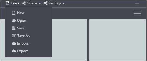
Instead of using the graphical user interface of WeStatiX you might want to write a JSON file and import it.
Below we briefly explain how a JSON input file is structured and how to define the geometry, properties, constraints and loads of your finite element model.
JSON file structure
All you have to do is write strings similar to the ones below.
Each file opens with:
   {
  "apiVersion": "0.0.1",
Then, define the nodes. The information you need to specify is of course the same information you need to provide when you create them from the graphical interface. Then, assign a name and the x,y and z coordinates. Look below for an example
  "nodes": [
    {
      "name": "AR1",
      "x": -7,
      "y": -120,
      "z": 0
    },
    {
      .....
    },
    {
      "name": "AR5_O",
      "x": 4,
      "y": 132,
      "z": 0
    }
  ],
Note that nodes and elements are numbered from 0, and not from 1 as in the graphical user interface!
So if i is the number identifying the node here and j is the number identifying the same node in the graphical interface, the two are linked by the relation i = j – 1.
You can define members by specifying start and end nodes.
"members": [
    {
      "name": "P1",
      "startNode": 23,
      "endNode": 135
    },
    {
      ....
    },
    {
      "name": "AR5_O",
      "startNode": 211,
      "endNode": 194
    }
  ],
To create shell elements, write the nodes that define them in order.
"shells": [
    {
      "name": "AR_11",
      "nodes": [
        0,
        1,
        22,
        21
      ]
    },
    {
      ...
    },
    {
      "name": "D_5",
      "nodes": [
        199,
        198,
        202,
        203
      ]
    }
  ],
If you import the JSON file at this point, if you have not made any errors the geometry will appear in the Viewport 3D.
Of course you can also define materials and sections! In order to comply with WeStatiX internal coding, however, it may be more convenient for you to define them from the graphical user interface.
"materials": [
    {
      "name": "C35_45",
      "materialType": "Standard",
      "materialId": 300048
    }
  ],
  "sections": [
    {
      "name": "AR",
      "sectionType": "Rectangle",
      "material": 0,
      "width": 6,
      "height": 3,
      "holeWidth": 3,
      "holeHeight": 1,
      "fillet": 0
    },
    {
      "name": "P",
      "sectionType": "Rectangle",
      "material": 0,
      "width": 1,
      "height": 2,
      "holeWidth": 0,
      "holeHeight": 0,
      "fillet": 0
    }
  ],
Constraints at the nodes.
Remember that if i is the number identifying the node here and j is the number identifying the same node in the graphical interface, the two are linked by the relation i = j – 1.
  "nodeSupports": [
    {
      "name": "FFF0",
      "node": 0,
      "dx": "F",
      "dy": "F",
      "dz": "F",
      "rx": "F",
      "ry": "F",
      "rz": "F"
    },
    {
      ....
    },
    {
      "name": "FFF211",
      "node": 211,
      "dx": "F",
      "dy": "F",
      "dz": "F",
      "rx": "F",
      "ry": "F",
      "rz": "F"
    }
  ],
Definition of member properties. Between the square brackets that follow “members” you can list the elements to which you want to assign the property.
Remember that, if i is the number identifying the element here and j is the number identifying the same element in the graphical interface, the two are linked by the relation i = j – 1.
"memberProperties": [
    {
      "name": "AR",
      "members": [
        0,
        1,
        .,
        .,
        .,
        25
      ],
      "section": 1,
      "rotation": 0,
      "startJointDx": "F",
      "startJointDy": "F",
      "startJointDz": "F",
      "startJointDrx": "F",
      "startJointDry": "F",
      "startJointDrz": "F",
      "endJointDx": "F",
      "endJointDy": "F",
      "endJointDz": "F",
      "endJointDrx": "F",
      "endJointDry": "F",
      "endJointDrz": "F"
    }
  ],
Shell Property Definition
  "shellProperties": [
    {
      "name": "DECK",
      "shells": [
        80,
        .,
        .,
        .,
        139
      ],
      "material": 0,
      "thickness": 2
    },
    {
      "name": "AR",
      "shells": [
        0,
        1,
        .,
        .,
        .,
        79
      ],
      "material": 0,
      "thickness": 3
    }
  ],
Even for loads, all you have to do is specify the element to which they apply and the various components.
"gravity": {
    "name": "",
    "group": "default",
    "gx": 0,
    "gy": 0,
    "gz": -9.80665
  },
  "shellPressures": [
    {
      "name": "traffic 9",
      "group": "q_traffic",
      "shell": 80,
      "reference": "Global",
      "px": 0,
      "py": 0,
      "pz": -9,
      "mx": 0,
      "my": 0,
      "mz": 0
    },

   ....
    {
      "name": "traffic 9",
      "group": "q_traffic",
      "shell": 103,
      "reference": "Global",
      "px": 0,
      "py": 0,
      "pz": -9,
      "mx": 0,
      "my": 0,
      "mz": 0
    },
    {
      "name": "traffic 2.5",
      "group": "q_traffic",
      "shell": 104,
      "reference": "Global",
      "px": 0,
      "py": 0,
      "pz": -2.5,
      "mx": 0,
      "my": 0,
      "mz": 0
    },
    ....
    {
      "name": "traffic 2.5",
      "group": "q_traffic",
      "shell": 139,
      "reference": "Global",
      "px": 0,
      "py": 0,
      "pz": -2.5,
      "mx": 0,
      "my": 0,
      "mz": 0
    }
  ]
}
}
Are you finished? Import the JSON file and run the analysis!